555 Timer Ic Schematic Diagram - Basic Theory IC 555 | IC schematics - It includes all of the wiring diagrams and instructions you need to get started.
555 Timer Ic Schematic Diagram - Basic Theory IC 555 | IC schematics - It includes all of the wiring diagrams and instructions you need to get started.. The 555 timer is a simple integrated circuit that can be used to make many different electronic circuits. It is a affordable, stable and user friendly ic in application such. In this tutorial, 555 timer ic is introduced. In the schematic above, notice that the threshold pin and the. Lm555 timer internal circuit block diagram.
Ic 555 timer is a one of the most widely used ic in electronics and is used in various electronic circuits for its robust and stable properties. Learn about the 555 timer and how it works in astable mode. Print the diagram in the centre of a sheet of paper create a circuit using the ics pin locations. Electronics tutorial about the 555 timer and how the 555 timer can be used as a 555 monostable or 555 bistable timer to generate timing pulses. In this tutorial, 555 timer ic is introduced.
Ticking Bomb Sound Circuit Diagram from circuitdigest.com If you still need a detailed understanding of the 555 timer. The 555 timer ic is an integral part of electronics projects. Electronics tutorial about the 555 timer and how the 555 timer can be used as a 555 monostable or 555 bistable timer to generate timing pulses. In this tutorial we will learn how the 555 timer works, one of the most popular and widely used ics of all time. 1 internal diagram of 555 timer. 555 timer ic is the most commonly used ics for timing and pulse generation applications. With this information you will learn how how the 555 works and will have the experience to build some of the circuits below. You can watch the following video or read the written tutorial below.
(1) for all available packages, see the orderable addendum at the end of the datasheet.
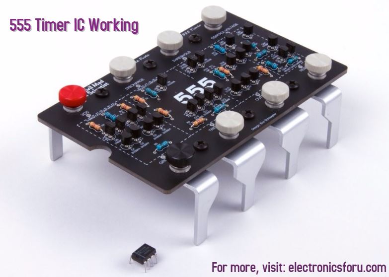
555 timer is an industrial standard ic existing from early days of ic. The 555 timer ic is most versatile linear integrated device introduced by signetics corporation in early 1970. By ligo george 555 circuits, electronics, ic 555, ic, timer 0 comments. 1 internal diagram of 555 timer. The internal block diagram and schematic of the 555 timer are highlighted with the same color across all three drawings to clarify how the chip is implemented:2. The 555 timer was introduced over 40 years ago. Taking apart a circuit board or module and reconstructing its complete schematic is a valuable skill. The 555 ic timer circuit above shows a very straightforward design where the ic 555 forms the central modified ic 555 toaster circuit diagram. (1) for all available packages, see the orderable addendum at the end of the datasheet. Theory of the working of this ic is discussed in detail along with it's basic introduction. Print the diagram in the centre of a sheet of paper create a circuit using the ics pin locations. The three fives discrete 555 timer kit from evil mad scientist laboratories is a faithful and functional transistor scale replica of the classic ne555 timer integrated circuit. 555 ic automatically switches back to stable state after some time, this time, for which the 555 stays in quasi stable state, is determined by the time constant of rc network in the circuit.
You can either follow the previous schematic or follow the breadboard wiring diagram below. This integrated circuit can be used in a variety of ways from which the basic one is to produce accurate. This article covers every basic aspect of 555 timer ic. • in the time delay mode, the delay is controlled by one external resistor and switch is moved back to position b. The block diagram of a 555 timer is shown in the figure.
IC 555 Timer Working: Pin Diagram, Specifications & Features from www.electronicsforu.com The 555 timer is one of the rst examples of a mixed mode ic circuit that includes both analogue and digital components. 555 timer ic is the most commonly used ics for timing and pulse generation applications. 555 timer is an industrial standard ic existing from early days of ic. They are very simple to understand if we take a look at the components present inside as shown below. It includes all of the wiring diagrams and instructions you need to get started. The 555 timer, designed by hans camenzind in 1971. The 555 timer was introduced over 40 years ago. Look at the circuit diagram.
• in the time delay mode, the delay is controlled by one external resistor and switch is moved back to position b.
Above schematic diagram shows the 555 timer monostable multivibrator circuit. By adding one or two external resistors and one capacitor the. Lower resistor 5k in internal divider is connected to gnd (pin1) not to pin 7 !!!! It includes all of the wiring diagrams and instructions you need to get started. Look at the circuit diagram. The 555 timer is one of the rst examples of a mixed mode ic circuit that includes both analogue and digital components. (1) for all available packages, see the orderable addendum at the end of the datasheet. The 555 timer ic is a very cheap, popular and useful precision timing device which can act as either a simple timer to generate single pulses or long time. You can watch the following video or read the written tutorial below. Block diagram for a 555 timer. The 555 timer is the one of the most versatile linear hybrid integrated circuit (ic) which is used in variety of pulse generation, timer and oscillator applications. The 555 ic timer circuit above shows a very straightforward design where the ic 555 forms the central modified ic 555 toaster circuit diagram. Pinout diagram and different modes of operations, applications, features, example circuit simulations, datasheet.
In the schematic above, notice that the threshold pin and the. The primary purpose of the 555 timer is the generation of accurately timed single pulse or oscillatory pulse waveforms. The 555 timer ic is most versatile linear integrated device introduced by signetics corporation in early 1970. It is a affordable, stable and user friendly ic in application such. The internal block diagram and schematic of the 555 timer are highlighted with the same color across all three drawings to clarify how the chip is implemented:2.
Adjustable Timer Circuit using 555 from www.theorycircuit.com Pinout diagram and different modes of operations, applications, features, example circuit simulations, datasheet. In the schematic above, notice that the threshold pin and the. 1 internal diagram of 555 timer. The internal block diagram and schematic of the 555 timer are highlighted with the same color across all three drawings to clarify how the chip is implemented:2. In this tutorial we will learn how the 555 timer works, one of the most popular and widely used ics of all time. Connect a 440uf capacitor between pins 1 and 6, make sure. Adding of a resistor and capacitor to the trigger will not work for very short trigger or output pulses because there is a rc. (1) for all available packages, see the orderable addendum at the end of the datasheet.
The 555 timer is a simple integrated circuit that can be used to make many different electronic circuits.


0 Komentar